
Thanks Peter from Australia for sharing with his mTech 3i on his Cougar Mill/Drill
He is using scale travel "220mm, 370mm and 420mm)
Below is the complete write-up by Peter:
INSTALLATION OF THE TECH-3i DRO ON MY COUGAR MILL/DRILL
This Chinese machine is is built to the popular ZX7550C pattern. It was built in around 2003.
I obtained it several years ago, from a manufacturer in Sydney who never used it, before winding up the business.
My first task was to bring the machine into the workshop from it's storage in the garage.

The X-axis position provided good machined surfaces and access.
The placement of the scale and it's cover restricts Y-axis travel by about 60mm,
so that a new stop was later fitted. All that was required to get final alignment was a shim behind the reader.

The Y-axis field left something to be desired. (See below.)
Firstly, the surfaces are painted with thick, uneven enamel.
Secondly, the area is barely wide enough to accommodate the scale, so the cover cannot be used.
For the scale I scraped all the paint off the surface, and mounted the scale as low as possible to
give me a narrow lip above for some protection to be devised in the future.
After some shims to correct alignment the the scale sits very nicely.

The reader was mounted using some of the machined aluminium plates provided in the excellent kit from TheDroStore.com.
To the right of the scale you may be able to see a tapped hole on the mill. I decided to use a piece of aluminium channel as a shield.
I am machining part of one side out of the channel to accommodate the scale body
and will attach the remaining complete channel side, using the tapped hole indicated.
A similar hole will be drilled to the left of the scale after preliminary fitting.
Throughout the install, there were lubrication ports to be preserved.
I was surprised this did not cause any problems.
Also I managed to dodge the slide locks on opposite faces of the machine.

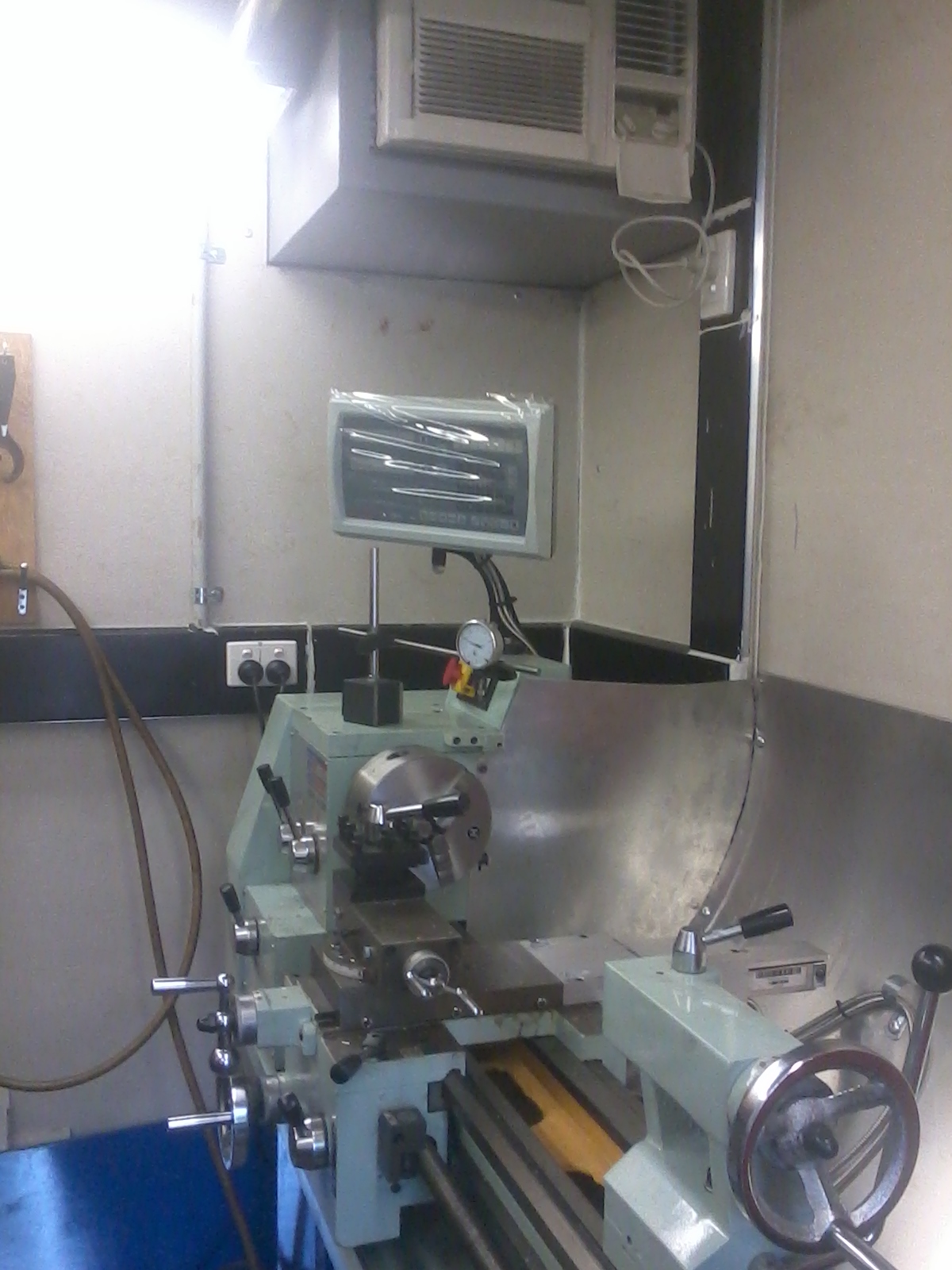
Fitting the Z-axis presented the paint problem once again. This time, however, I used a slightly different approach.
By scraping the paint carefully, I managed to obtain a usable surface, and with the help of suitable shims,
the test indicator (seen above) proved that scale alignment was satisfactory.
Once again the aluminium mounting hardware provided proved excellent to carry the Z-axis reader.
A piece of angle, trimmed down, a bit more paint scraping and a shim mounted on the knee and the job is nearing completion.
Covers were fitted to the X and Z-axis scales, with a small plate glued to the top of the Z-axis cover to help
protect it from falling coolant and swarf. (See below.)

Installing the readout went smoothly. Suitable positions were available and a transformer in the pedestal
provides 240v to power the display. The last photo shows the display in use and on the table the
shield for the Y-axis scale partly machined.
This is my very first milling operation. So far so good. No broken cutters, etc.

Considering that I have never attempted anything like this exercise before I am very pleased with the result.
I must say the kit provided, Scott's manuals and his other help have been confidence building and a big part
of completing the task at hand. As many others have commented, there was a surplus of materials and a choice of install methods.
Many thanks,
Peter Browne
Australia


